


 +86 18310268158

Sheet Metal Tolerance Standards: Process Cross-Reference
Sheet metal tolerance standards decide whether a part fits or fails. Buyers often specify a standard without knowing the factory default. This page maps each process to its governing tolerance standard. We have produced custom metal parts in Nanpi, Hebei since 1999.
How to use this page:
- Jump to the process table to find the standard for your operation.
- Use the ISO 2768-1 table to size your callouts.
- Read the entity facts to verify the source.
Why a Tolerance Cross-Reference Exists
General tolerance classes keep drawings short. They also hide assumptions that cause disputes. Three questions matter before any RFQ:
- Which class applies when the drawing is silent?
- Which features need explicit callouts?
- Which inspection method proves conformance?
Process to Standard Mapping
| Process | Referenced standard | What it controls |
|---|---|---|
| Laser cutting | ISO 2768-1 (m); drawing callouts | Part outline, hole position, edge quality |
| Press brake bending | ISO 2768-1; ASME Y14.5 when called | Bend angle, bend position, flat length |
| Stamping | ISO 2768-1; die-controlled tolerances | Form dimensions, thickness variation |
| Deep drawing | ISO 2768-1; die-controlled tolerances | Flange size, part height, wall variation |
| Welding | ISO 3834; AWS D1.1 (steel) / D1.2 (aluminum) | Joint geometry, weld integrity |
| Surface finishing | ISO 1461 (HDG); ASTM A967 (passivation); ISO 7592 (anodizing) | Coating thickness, surface integrity |
| Final verification | ISO 10360 (CMM); AS9102 (FAI) | Measured dimensions, documented results |
If your drawing cites no tolerance, ISO 2768-1 medium (m) is our default. Explicit GD&T callouts override the general class for the features they control.
ISO 2768-1 General Tolerance Classes
ISO 2768-1 defines four classes for linear and angular dimensions. The class letter appears on the drawing or spec sheet. These sheet metal tolerance standards tables apply to sheet up to 2 m.
| Nominal size (mm) | f (fine) | m (medium) | c (coarse) | v (very coarse) |
|---|---|---|---|---|
| 3 – 6 | ±0.05 | ±0.1 | ±0.2 | ±0.3 |
| 6 – 10 | ±0.05 | ±0.1 | ±0.2 | ±0.5 |
| 10 – 18 | ±0.05 | ±0.1 | ±0.3 | ±0.5 |
| 18 – 30 | ±0.05 | ±0.1 | ±0.3 | ±0.5 |
| 30 – 50 | ±0.07 | ±0.1 | ±0.3 | ±0.8 |
| 50 – 80 | ±0.07 | ±0.2 | ±0.4 | ±1.0 |
| 80 – 120 | ±0.10 | ±0.2 | ±0.4 | ±1.2 |
| 120 – 180 | ±0.10 | ±0.3 | ±0.5 | ±1.6 |
| 180 – 250 | ±0.15 | ±0.3 | ±0.7 | ±2.0 |
| 250 – 315 | ±0.20 | ±0.4 | ±0.8 | ±2.4 |
| 315 – 400 | ±0.25 | ±0.5 | ±1.0 | ±3.0 |
| 400 – 500 | ±0.30 | ±0.5 | ±1.0 | ±3.5 |
Class guidance:
- m (medium) suits most sheet metal work. It balances cost and fit.
- f (fine) suits functional dimensions that must fit mating parts.
- c (coarse) suits housings and non-critical structure.
- v (very coarse) suits large brackets and cosmetic frames.
Angular tolerances follow the same class system in ISO 2768-1. Specify the angular class separately when bend angles are critical.
Typical Tolerances by Process
The values below are typical holding tolerances for sheet up to 6 mm. They are starting points, not guarantees. Exact values are confirmed per drawing before production release.
| Process | Typical linear tolerance | Typical angle tolerance | Main driver |
|---|---|---|---|
| Laser cutting | ±0.1 mm | – | Beam focus, material thickness |
| Press brake bending | ±0.5 mm flat length | ±0.5° to ±1° | Tooling, K-factor |
| Stamping | ±0.1 mm per die | – | Die design, springback control |
| Deep drawing | ±0.1 – 0.3 mm flange | ±1° side taper | Material flow, die gap |
| Weldment | ±0.5 mm fit-up | ±1° | Fixturing, weld distortion |
Deep Drawing Tolerance Detail
Deep drawing is a core form process for this factory. We draw, redraw and spin on presses from 60T to 400T. Our largest press is a 400T single-point machine.
| Parameter | Typical tolerance | Main driver |
|---|---|---|
| Flange dimension | ±0.1 – ±0.3 mm | Die gap, blank size |
| Part height | ±0.5 mm | Draw depth, springback |
| Wall thickness variation | within ±5% of base | Material grade, lubrication |
| Side taper | ±1° | Draw reduction per pass |
Deep-drawing tolerance depends on material behavior. Copper alloys stretch predictably. Stainless thins differently across grades. Send material and shape, and we confirm achievable values in the quote.
GD&T: ASME Y14.5 vs ISO GPS
GD&T adds geometric controls beyond size tolerances. ASME Y14.5-2018 is common in North American drawings. ISO GPS, including ISO 1101, is common in EU drawings.
- Flatness, perpendicularity and position are our most requested controls.
- We quote to both symbol systems.
- Tell us which system your drawing uses.
- GD&T callouts override ISO 2768 for the features they control.
How Tolerances Affect Cost
Tolerance strategy is a cost decision, not only a quality one.
- Fine tolerances on every dimension raise cost without fit benefit.
- Omitting the general tolerance class invites inspection disputes.
- Mixing unit systems (mm and inch) on one drawing causes rework.
- Forgetting bend deduction makes the flat pattern wrong.
Specify per feature group. Mark critical dimensions with f or explicit GD&T. Let the rest default to m.
Drawing Conventions We Work With
- Units: millimeters by default; mark inches on inch-based drawings.
- Projection: first-angle or third-angle; mark it on the title block.
- Bend line: centerline by default unless marked A-side (inside).
- Radius: state inside radius and angle for every bend.
- Deburring: sharp edges broken 0.1 mm minimum unless noted.
- Threads: mark pitch and depth; we tap after forming.
Keep this page as your sheet metal tolerance standards reference.
Entity & Certification Facts
- Entity: Nanpi Xinjiuxinji Hardware Manufacturing Co., Ltd.
- Factory operating since 1999; legal entity registered 2020.
- Location: Nanpi County, Cangzhou, Hebei, China.
- 120 staff, including 19 engineers.
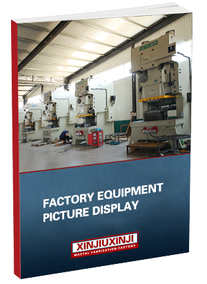
- 40+ presses from 60T to 400T.
- 6 kW fiber laser cutting.
- 70,000+ different types of custom metal parts produced.
- The group operates under ISO 9001:2015.
- Certificate no. ZTZL28025Q1049R0S, valid until July 6, 2028.
- Certificate holder: Cangzhou Xinjiuxinji Import And Export Co., Ltd.
- CMMs are verified to ISO 10360.
- First article reports per AS9102 are available on request.
FAQ
What tolerance class do you apply by default?
ISO 2768-1 medium (m) covers all features without an explicit callout. You can override per feature in the drawing.
Can you hold tighter than ISO 2768 f?
Yes, for critical dimensions, subject to inspection cost. CMM verification is available for those features.
Which GD&T standard do you read?
ASME Y14.5-2018 and ISO GPS. Tell us which standard your drawing uses.
How do you prove conformance?
CMM reports from machines verified to ISO 10360. FAI reports per AS9102 on request.